
The surface finishing process was performed by REM Surface Engineering, using their Extreme ISF Process®. This process combines a chemical polishing (CP) operation followed by a chemical mechanical polishing process (CMP). The CP was performed by immersion in a robot controlled chemical polishing bath. The CMP was performed in a 30 L circular vibratory bowl with a mix of non-abrasive ceramic media. The chemistry and dosing used for CP and CMP, as well as the media mix composition, shapes, and sizes, are the proprietary information of REM Surface Engineering and were not disclosed in the presentation.
Turning to the first of the case study examples, Fig. 2 shows the surface texture progression during the CP process of an PBF-LB (Ti-6Al-4V) specimen with porosity problems at the contour/hatching overlap region. It can be observed that most of the surface-related defects were remediated during the first 100 μm of surface metal removal (SMR) (Fig. 2, top right). The partially sintered/melted powder was eliminated and the surface profile peaks were partially planarised. Further processing eliminated most of the peaks. The deep valleys that were still present were significantly shallower and rounded, with a considerable planarisation level at 150 μm of SMR. At 175 μm of SMR, porosity associated with an unsuccessful overlap between the hatching pass and the contour was uncovered. This could usually be remediated with further processing at the expense of more sacrificial metal. This type of problem can be prevalent if extra care is not taken during the build process. Nevertheless, using a relatively inexpensive, fast, and easy CP process can check if some problems like this, or lack of fusion at the near-surface, occurred during the manufacturing process.
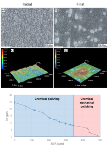
Fig. 3 Microscope images at 100 X magnification (a and b) with their 3D representations (c and d) of the surface of PBF-EB Ti-6Al-4V as-built tensile specimens, and the final surface after surface finishing (b and d). Average surface roughness (Ra) progression per surface material removal through the surface finishing operation (bottom). The blue area on the plot shows the CP progression and the red area shows the CMP progression [1]
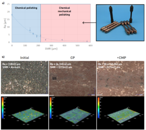
Fig. 4 Average surface roughness (Ra) reduction per surface material removal through the surface finishing operation of PBF-LB GRCop-42, first CP followed by CMP (a). The blue area on the plot shows the CP progression, and the red area shows the CMP progression [1]
The second case study focussed on PBF-LB GRCop-42 (Cu-4%Cr-2%Nb). GRCop-42 is a high-strength, dispersion-strengthened copper alloy with excellent conductivity, currently used in liquid rocket engines by NASA and other commercial space companies. Fig. 4 shows the surface texture progression for typical non-HIPed specimens of this alloy through the surface finishing operations. The as-built components show surface texture features overtaken by the partially sintered/melted powder on the surface, with Ra = (18 + 2) μm. The initial surface texture improved remarkably through the CP process; in this specific example, by removing around 200 μm from the surface, a Ra reduction of up to 78% was achieved; followed by the CMP process, reaching the lower possible Ra, where values under 0.6 μm were achieved (Fig. 4).
Finally, the PBF-LB IN625 case study was considered. The surface texture optimisation was performed by removing 400 μm from the surface by CP followed by 100 μm by CMP. The initial surface roughness of the as-built specimens was Ra = (8.3 + 0.5) μm and Ra = (7.5 + 0.2) for the HIPed samples. After applying CP + CMP, the final surface roughness was Ra = (1.1 + 0.6) μm for the non- HIPed samples and Ra = (0.07 + 0.01) μm for the HIPed samples. The non-HIPed sample surfaces showed significant shallow pits from the overall porosity, while the HIPed samples’ surfaces were perfectly smooth.
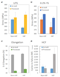
Fig. 5 Tensile strength (a), 0.2% yield strength (b), elongation (c), and uniaxial tensile high-cycle fatigue (Load at 434 MPa, room temperature, R = 0.1, and 60!Hz) of PBF-LB IN625 specimens before and after surface finishing and HIPing [1]
Download Resource
Please fill out the information below to receive the selected resource.