
Specimen
Three sets of FZG gears were tested; all gears were the sliding-speed-balanced tooth configuration “FZG”, type C-GF. Each set was comprised of a gear and a pinion. Geometric data of the gears, tooth quality, heat treatment and material data are consistent across all of the gear sets. Refer to Table 1 for geometric data of the gears and Table 2 for tooth quality heat treatment and material data.


Table 1: Geometric data of the test gear and pinion teeth for the BTGS Material 16 MnCr 5 ( DIN 1721 0)

|
Heat treatment |
Case carburized: 750 HV 1 |
|
Tooth quality |
5 (DIN 3962) |
| Inital Surface Roughness | Ra = 0.5 ± 0.1 μm Finish Maag finish |
Table 2: Test gear specifications for C-GFU specimens for all gears prior to superfinishing
All three sets were specified to have an initial roughness average (Ra) of 0.5 ± 0.1 μm. One set was to be used for baseline comparison. The two remaining sets were superfinished by vibratory finishing as well discussed elsewhere. [3,4] As a result of the superfinishing, the surface Ra was under 0.15 μm. Both sides of the gear teeth were tested.
Test conditions
In accordance with DIN51354 the BTGS is performed on a standard FZG warping test bench with splash lubrication. The test gear is installed on the motor shaft while the test pinion is the driving gear. The standard test conditions for the DGMK BTGS were used, and are compiled in Table 3, while Table 4 contains torque and Hertzian stresses for each power level.
| Pinion rotational speed | 8.3 meters/sec |
| Circumferential speed on the working circle | 0.00383 meters/sec |
| Driving test gear | Pinion |
| Lubrication | Splash lubrication about 1.5 liters |
| Oil sump temperature | 90±2°C |
| Running time for run-in (power level 3) |
~ 1.0 hr |
| Running time per power levelinstagedtest |
~ 16 hr 6 |
Table 3: Test conditions in BTGS.
|
Power level |
Torque at the pinion in [Nm] |
Hertzian stress in the rolling point pc in [N/mm2] |
| 3 (run-in) | 28.8 | 510 |
| 7 | 132.5 | 1093.9 |
| 9 | 215.6 | 1395.4 |
Table 4: Power levels of the BTGS performed.
The lubricant used was FVA 2 +2% LZ 677A. This oil and additive is known to have relatively low micropitting resistance, and was selected for this test based on this criteria. Since operational temperature is a separate factor of a lubricant’s micropitting resistance, the sump temperature in all three tests was held constant. A thermostat held the oil sump at 90 oC on all six test runs to ensure that the lubricant’s additive package would perform equally across all tests.


The test consisted of a ~1.0 hour run-in cycle at power level 3 followed by ~16 hour duration loaded cycles at power level 7 and 9 respectively. The gears were measured and observed following each loaded cycle. Each measurement was of three teeth spaced equally around the circumference of the gear. The measurement consisted of a profile form deviation, and the final measurement included a picture of the final condition of the three tooth flanks that were measured.
The test for micropitting on the FZG gears is correlated to the maximum profile deviation, or wear. This correlation is due to the deformation caused by micropitting. As such, the tests conducted for this study use this profile deviation (wear) to determine the effects of superfinishing on micropitting reduction.
Data
Concluding all test runs, each gear set was classified into BTGS low, medium, or high resistance to micropitting. The BTGS classifications are defined relative to when the wear exceeds the 7.5 μm failure limit. As shown in Table 5, BTGS low fails after the power level 7 loaded cycle, BTGS medium fails after the power level 9 loaded cycle, and BTGS high does not fail by the conclusion of testing.
Table 5: Categorization of micropitting resistance.
| Micropitting resistance | Criteria for micropitting resistance classification. |
| BTGS-low | Wear after Power Level 7 exceeds 7.5 μm |
| BTGS-medium | Wear after Power Level 9 exceeds 7.5 μm |
| BTGS-high | Wear after Power Level 9 does not exceed 7.5 μm |
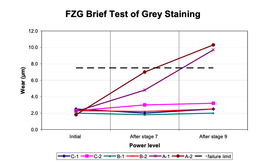
In two runs, the gears specified to have a Ra of 0.5 ± 0.1 μm (or non- superfinished, baseline gears) had average micropitting resistance, according to the researcher’s experience. The two runs exhibited the same results with minimum dispersion. The first run, A-1, had an arithmetic roughness average (Ra test) of 0.48 μm (where Ra test = ((Ra gear + Ra pinion) / 2)) prior to testing and ended with 9.7μm wear. The second run, A-2, had a Ra test of 0.55 μm initially and finished with an wear of 10.3 μm. Both tests resulted in a failure after power level 9, and confirm that the lubricant selected exhibits average micropitting (BTGS-medium) for the investigated operational temperature range of 90 °C. The progression of the wear of these trials is present in Graph 1, and images of the final condition of the three equally spaced tooth flanks along the circumference are given in Figures 1 and 2.

Figure 1: Evidence of micropitting on first baseline run A-1.

Figure 2: Evidence of micropitting on second baseline run A-2.
FZG Brief Test of Grey Staining Baseline
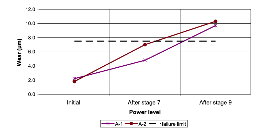
Graph 1: Stage by stage breakdown of the wear from BTGS on A-1 and A-2.
In the first test of superfinished FZG C-GF gears, the Ra test of the controlled tooth flanks was 0.10 μm and 0.09 μm for the first and second run respectively. The first run had a wear 2.5μm while the second had 3.2 μm, shown in Graph 2. The lack of any discernible micropitting is shown in Figures 3 and 4.
Figure 3: Image of tooth flanks following BTGS testing with no micropitting from test B-1.

Figure 3: Image of tooth flanks following BTGS testing with no micropitting from test B-1.

Figure 4: Image of tooth flanks following BTGS testing with no micropitting from test B-2.
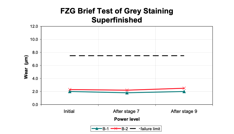
Graph 2: Stage by stage breakdown of the wear from BTGS on B-1 and B-2.
In the second test of superfinished FZG C-GF gears as processed by vibratory finishing, the Ra test of the tooth flanks was were 0.14 μm and 0.11 μm for the first and second run respectively. The first run concluded with a wear of 2.0 μm while the second run had a measured wear of 2.5 μm. As seen with first set of superfinished gears, wear for this second set of superfinished gears was minimal as illustrated in Graph 3. The lack of any discernible micropitting is shown in Figures 5 and 6.
Figure 5: Image of tooth flanks following BTGS testing with no micropitting from test C-1.

Figure 5: Image of tooth flanks following BTGS testing with no micropitting from test C-1.

Figure 6: Image of tooth flanks following BTGS testing with no micropitting from test C-2.
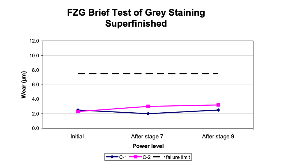
Graph 3: Stage by stage breakdown of the wear from BTGS on C-1 and C-2.
On the baseline set, micropitting was observable by the naked eye on the gear flank. However, on both sets of superfinished FZG gears, micropitting was undetectable. By lowering the Ra to approximately 0.10 μm, wear was reduced.
The data plotted together in Graph 4 shows that the only failures were A-1 and A- 2 which were the baseline samples that were ground with no superfinishing. None of the four superfinished runs came close to the failure limit even after the completion of the test. Additionally, it was noted that there was no discernible region on the superfinished gears that had micropitting. There was also not any increase in the wear after the BTGS.
Graph 4: Wear summary. A-1 and A-2 are baseline while B-1, B-2, C-1 and C-2 were
superfinished. The failure limit is defined at 7.5μm.
Conclusions
Superfinishing significantly reduces micropitting, even on the BTGS which was designed to quickly induce micropitting. These findings stress the importance of surface finish for resisting the formation of micropitting.
This information could be beneficial to the lubrication industry. Superfinished gears may use a simplified additive package.
Since the superfinished surfaces did not fail during the BTGS testing, the superfinished surfaces were further studied in the more rigorous standard FZG micropitting test. These results will be provided in Part II of this paper.
The authors would like to thank: Technical University of Munich, where the testing was performed as well as G. Steinberger, P. Oster and B.-R.Hohn who were responsible for completing the testing, as well as FZGmbH and Voith Turbo GmbH & Co. KG. for their parts in making the data available.
References:
[1] Joachim, Franz, Norbert Kurz, and Bernhard Glatthaar. “Influence of coatings and surface improvements one the lifetime of gears”. International Conference on Gears. March 13-15,2002. Munich Germany. VDI Report 1665. [2] Forschungsvereinigung Antriebstechnik, E.V, “FVA Information sheet” Research Projects Nr. 54/I-IV, 1993 [3] Krantz, T.L., M.P. Alanou, H.P. Evans, R.W. Snidle. “Surface Fatigue Lives of Case- Carburized Gears With an Improved Surface Finish,” NASA/TM-2000-210044, 2000. [4] Arvin, J., A. Manesh, M. Michaud, G. Sroka, and L. Winkelmann. “The Effect of Chemically Accelerated Vibratory Finishing on Gear Metrology,” 02FTM1, AGMA Fall Technical Meeting, St. Louis, MO, October 2002.Download Resource
Please fill out the information below to receive the selected resource.