Measuring Tooth Flank Roughness
By : Mark Michaud ,

By : Mark Michaud ,
Gear performance has continuously increased over the past two decades. Improvements in metals, heat treatments, geometry, and lubrication are just a few of the sources of these improvements. For gears operating in high load, EHL-type conditions, tooth flank finishes have experienced a similar improvement trend. These tooth flank finish improvements minimize the risk of surface distress failures such as wear, fretting, scuffing, macro and micropitting, or to reduce vibrational excitation (tonality). As such, it is not uncommon today to have highly loaded gears specified and manufactured to tooth flank finishes of Ra < 4 µin (Ra < 0.1 micron).
These tooth flank finishes have been achieved from improved grinding, honing, or superfinishing technology. However, with improved flank finishes, confusion, uncertainty, and errors have arisen regarding the specification, measurement, or documentation of flank roughness. Part of these problems stems from the fact that there will always be some variation of roughness across a given flank surface. Furthermore, the range of variation can increase depending on the finishing process. Fortunately, the current state of the art of gear manufacturing produces tooth flank finishes with reasonably small surface finish variation such that the gear performance can be generally predicted.
The unavoidable roughness variation of a given tooth flank is generally small and can easily be accounted for in the tooth flank roughness specification and manufacture without a loss in gear performance. However, other sources for flank roughness measurement problems can result in poor gear performance and are [1, 2, and 3]:
Even with proper roughness measurement, there will be some variation in the results. Gear designers and manufacturers need to understand and accept this unavoidable variation in surface roughness. The first step in this understanding starts with the realization that no surface can be exactly equal to a single roughness number. Too often a flank roughness is specified or reported to be Ra = XX µin. However, a surface roughness can either be:
Fortunately, there are a small number of ISO Specifications within the GPS (Geometrical Product Specifications) Matrix of Standards that can be used to reduce the problems that can lead to unacceptably large or erroneous roughness measurement. If these ISO Specifications are understood and applied correctly, the significant variations or errors can be reduced such that the roughness measurements are accurate, repeatable, and reproducible. This will be the first in a series of articles on the subject of Tooth Flank Roughness Measurement based on these ISO Standards.
The goal of these articles will be to describe how to carry out and document pragmatic, accurate, repeatable, and reproducible roughness measurement of tooth flanks. This article will describe the characteristics of the measurement equipment needed to analyze surface texture and achieve some of the above goals. This article is about the Contact Stylus Profilometer based on ISO 3274: 1996. [4]
It should be noted that this and the following articles will assume that environmentally induced roughness measurement variations (i.e. from forge shop vibrations) will not be an issue in achieving these goals. The author is familiar with many gear manufacturing facilities where the profilometry is successfully carried out adjacent to the flank finishing equipment without the introduction of environmentally induced errors. Modern profilometer setups can easily coop with forklift traffic, hoists, gear grinding equipment, and the like without the introduction of roughness measurement errors. For the purpose of these articles:
Surface texture is made up of three elements: its roughness, its waviness, and its form. The surface roughness is made up of the process marks or grinding asperities produced by the cutting tools or machining process. The roughness is characterized by short wavelengths (i.e. short spaced surface imperfections or asperities). The waviness is typically produced by machining instabilities or cutting tool imbalances (i.e. poor grinding stone dressing) and the like. Waviness is characterized by longer wavelengths compared to the roughness, which is superimposed within the waviness. Form is the general shape of the surface (i.e. an involute tooth flank), ignoring the variations due to the roughness and waviness. Surface waviness and form are rarely found in isolation (i.e. there are rarely truly flat surfaces) and are treated the same by the profilometer. The fundamental function of a contact stylus profilometer is to separate the three elements of a surface and to analyze the waviness and roughness separately. The issue is how to separate surface irregularities into roughness versus waviness. This separation is accomplished by the profilometer through the use of filtering and is a critical capability of the instrument.
For a tooth flank, its surface texture is described by its waviness, its roughness and its lay. The surface lay is created during manufacturing of the flank by the primary direction of travel of the machining process used. The lay is the primary direction of the roughness irregularities. Lay can have a significant impact on gear performance based on how it effects the movement of lubricant between mated teeth. Lay is addressed in these articles only in regards to how a profilometer is setup and operated to produce the roughness measurement.
To understand profilometer filtering, understand that a surface is nothing more than a series of peaks and valleys (asperities) of varying heights and with various distances between them. From this perspective, a surface is made up irregularities of varying wavelengths and varying heights. The profilometer filter separates out different wavelengths (the filter wavelength is called a cut-off) of the surface being measured so that they can be analyzed separately. The analysis results in determining the roughness and waviness of the surface.
Early surface measuring instruments used electronic analog filters known as 2CR filters. The 2CR stands for two capacitors and two resistors. These electronic filters suffer from phase distortion due to their electronic components. As such, separation of the waviness from the roughness of a surface can be unsatisfactory using this type of filter.
Today, ISO 3274 compliant profilometer instruments use phase corrected filters, preferably Gaussian filter in the case of tooth flank roughness measurement. These types of filters drastically reduce the distortion when separating waviness from roughness. These filters are very robust, but can only be implemented by mathematical algorithms using digital computer processing. A phase corrected Gaussian filter commonly used in today’s profilometers complies with ISO 3274, and can be said to be the basis for modern day profilometry.
It must be noted that the distortion by 2CR filters can be minimized if the recommended sampling lengths (cut-off wavelength) are followed as per ISO 4288:1996. (ISO 4288; the procedures for roughness measurement (to be discussed in a later article). However, a minimal distortion can be achieved only in regards to the Ra and Rz roughness parameters. As such, 2CR filters can comply with ISO 3274 in regards to Ra and Rz, but for other types of roughness parameters the distortion can be significant. Since many more roughness parameters are important in today’s profilometry, 2CR filters are generally no longer available or used in profilometry.
How does the profilometer’s phase correct filter work? In basic terms, a cut-off (specific wavelength) is a filter and is used as a means of separating the irregularities found on a surface. Cut-offs have a numerical value that, when selected, will reduce or remove the unwanted wavelengths (irregularities) from the surface analysis. For example, a roughness filter cut-off of 0.8 mm will allow wavelengths below 0.8 mm to be assessed, or included in the roughness measurement, while wavelengths above 0.8 mm are reduced in amplitude, or removed. Inversely, for a waviness filter cut-off of 0.8 mm, wavelengths above 0.8 will be assessed while wavelengths below 0.8 will be reduced in amplitude, or removed. By this filtering method, the surface measurement can be separated into the short wavelength roughness profile or the long wavelength waviness profile. See Figure 1 for a graphical presentation of an ISO 3274 compliant profile filtration of a surface.

A detailed description of the filter characteristics needed to comply with ISO 3274 is beyond this article’s scope, but can be found in ISO 11562 [5]. Fortunately, the four nominal values for the roughness cut-off wavelengths of the profile filter cited in ISO 3274 are; 0.08 mm; 0.25 mm; 0.8 mm; 2.5 mm; 8.0 mm. The roughness cut-off wavelength is symbolized by λc.
ISO 3274 completes the filtration specification by citing the relationship between the cut-off wavelength λc, the stylus tip radius and the roughness cut-off ratio (the ratio of the cut-off wavelength to the trace sample length (λc/λs) in a simple table. This table is the basis for all roughness measurement setup and procedures.

 Figure 2: Contact Stylus Profilometer schematic.
Given the proper filtration capability, what other characteristics are needed in a profilometer to comply with ISO 3274? The Specification cites:
Note: A recording capability is also recommended in ISO 3274.
Note: A separate article will detail the characteristics, use and maintenance of profilometer diamond tipped styli.

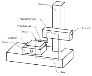
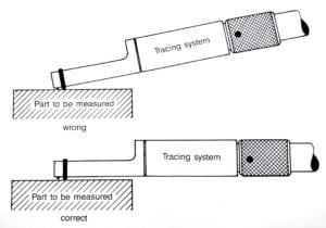
Modern day contact stylus profilometers that comply with ISO 3274 have ISO compliant filtration capabilities that minimize distortion using a phase correct Gaussian filter recommended for gear flank roughness measurement. Today’s instruments come equipped with tip orthogonality (positioning) boundaries (see Figure 4 for orthogonal tip positioning) and form (shape) correcting limits. These features result in surface measurements that can be completed easily, and with reasonable accuracy.

These instruments are robust, simple to operate with minimal training for set up and operational procedures, and can reproducibly measure flank roughness. A typical shop floor, ISO 3274 compliant profilometer set up will cost approximately $25,000 to approximately $35,000. This profilometer forms the basis for a pragmatic, accurate, repeatable and reproducible tooth flank roughness measurement and documentation capability in a gear manufacturing environment. Figures 5 and 6 show such a profilometer set up in a gear processing facility.

 Figure 5: Pragmatic Profilometer set up measuring a large diameter gear.
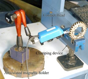 Figure 6: Pragmatic Profilometer set up measuring a small diameter gear.
Future articles will discuss the profilometer stylus, set up and measurement procedures, and the proper specification-documentation of roughness.
Please fill out the information below to receive the selected resource.
Please fill out the information below to receive the selected resource.