From Fixed Processes to Flight Parts: How REM’s Advanced Surface Finishing Supports NASA JPL’s AM Innovations
By : Justin Michaud ,
![Concept design for the Mars Sample Return (MSR) Fetch Helicopter [11]](https://remchem.wpenginepowered.com/wp-content/uploads/2025/07/metal-am-july25-fig16.jpg)
By : Justin Michaud ,
REM Surface Engineering has worked with NASA’s Jet Propulsion Laboratory (JPL) for decades to develop surface finishing processes for metal components used in space missions – more recently including those produced by Additive Manufacturing. Drawing on its aerospace and medical experience, REM has adapted its Isotropic Superfinishing (ISF(r)) and Chemical Polishing (CP) technologies to address the roughness and surface variability of AM parts. In this article, REM’s Justin Michaud and Agustin Diaz trace the evolution of that work, culminating in the development of ultralight, crushable lattice structures for the Mars Sample Return mission.
REM Surface Engineering has been supporting NASA’s Jet Propulsion Laboratory (JPL) missions since well before the lab turned to Additive Manufacturing for flight hardware. The company’s ISF(r) Process – a chemically assisted, non-directional surface finishing technology – has been used in multiple Martian Rover programmes to finish extremely small, high-precision gears and components, such as the part shown in Fig. 1. Beyond the space sector, the ISF Process has been deployed for more than three decades in critical, high-performance gear applications across aerospace and other industries.
As one of the first – if not the first – non-tool-path-guided surface polishing processes applied to precision gears, the ISF Process is perhaps the most rigorously and comprehensively tested polishing method outside of traditional machining. It is essentially a chemically assisted tumbling approach, leveraging alloy-matched chemistries and controlled, typically self-limiting surface reactions to achieve precise material removal and surface refinement [1].

Fig. 1 Prototype Martian Rover gear from the early 2000s (Courtesy REM Surface Engineering)
The benefits of the process – more generally referred to as isotropic superfinishing, a term REM coined to describe the ultra-low roughness, non-directional surface texture it produces – first attracted the interest of the aerospace industry in the 1990s for power transmission gears. Companies including Sikorsky [2] and Bell Helicopter [3, 4] have publicly acknowledged their use of REM’s technology for helicopter and vertical takeoff and landing aircraft (Fig. 2).
From Aerospace to AM: Adapting Surface Finishing to Meet Unique Challenges
This association with the aerospace sector led REM into the world of metal AM and, ultimately, into supporting JPL’s metal AM programmes. However, this transition did not happen overnight. REM’s journey from gear and machined component surface polishing technology provider to approved metal AM surface finishing supplier for JPL (and others) began nearly fifteen years ago. In 2012, CalRAM, Inc contacted REM about a programme it was undertaking with Northrop Grumman and UES Technology [6] focused on Ti-6Al-4V.
REM had worked with Ti-6Al-4V since the 1980s in support of medical applications and aero-engine compressor blades (see Fig. 3), so a titanium surface finishing project seemed straightforward. However, when the fatigue specimens and Mars Pathfinder components produced by Electron Beam Powder Bed Fusion (PBF-EB) arrived at REM’s Texas location – the first metal AM components REM had ever seen – they looked nothing like the milled or machined parts the company was used to handling (see Fig. 4).
At the time, REM had been experimenting with alternative purely chemical processes to support various experimental left ventricle assist device (LVAD) components, whose geometries and material removal requirements were not fully suited to the ISF Process.
After recovering from the initial shock of the roughness and surface texture of the PBF-EB/Ti-6Al-4V components, REM began testing both its traditional ISF Process and its then-experimental chemical process. A two-step approach – chemical treatment followed by the ISF Process – was ultimately adopted. This combination significantly reduced surface roughness; however, the parts still retained a much rougher texture than the typical final components produced by REM, primarily due to elevated levels of residual waviness (see Fig. 5).

Fig. 2 Future Advanced Rotorcraft Drive System (FARDS) main rotor gearbox (MRGB) gearshaft (publicly acknowledged as having undergone the ISF Process at AHS Forum 2017 [5])

Fig. 3 Traditionally manufactured Ti-6Al-4V compressor blade segment shown after REM’s ISF Process (Courtesy REM Surface Engineering)

Fig. 4 Example of PBF-EB/Ti-6Al-4V components in their as-built condition (Courtesy REM Surface Engineering) REM & NASA: surface finishing for AM
However, time constraints meant REM had to return the components to CalRAM so that testing and evaluation could proceed. To everyone’s surprise, REM’s specimens outperformed a competitive abrasive polishing process – which had achieved a much lower roughness value – in uniaxial high-cycle fatigue testing (see Fig. 6). REM’s samples only underperformed compared to specimens that were additively manufactured as solid cylinders and then fully machined to final dimensions – an approach REM considers not directly comparable, given the substantial material removal from the gauge section of those samples.
This unexpected result marked REM’s entry into the metal AM market. The experimental chemical process evolved into REM’s Chemical Polishing (CP) technology, and the ISF Process was adapted from its original goal of minimising material removal (typically 5-15 μm per surface) while achieving ultra-low roughness (<0.1 μm Ra), to also accommodate more aggressive removal levels. This adaptation was necessary to address the inherent surface waviness of metal AM components.
To distinguish between the two approaches, REM began using the term Chemical-Mechanical Polishing (CMP) to describe this more AM-tailored variant of the ISF Process which was often used subsequent to REM’s Chemical Polishing process. Ultimately, REM opted for the tradename Extreme ISF Process to refer to both methods, used either independently or in sequence.
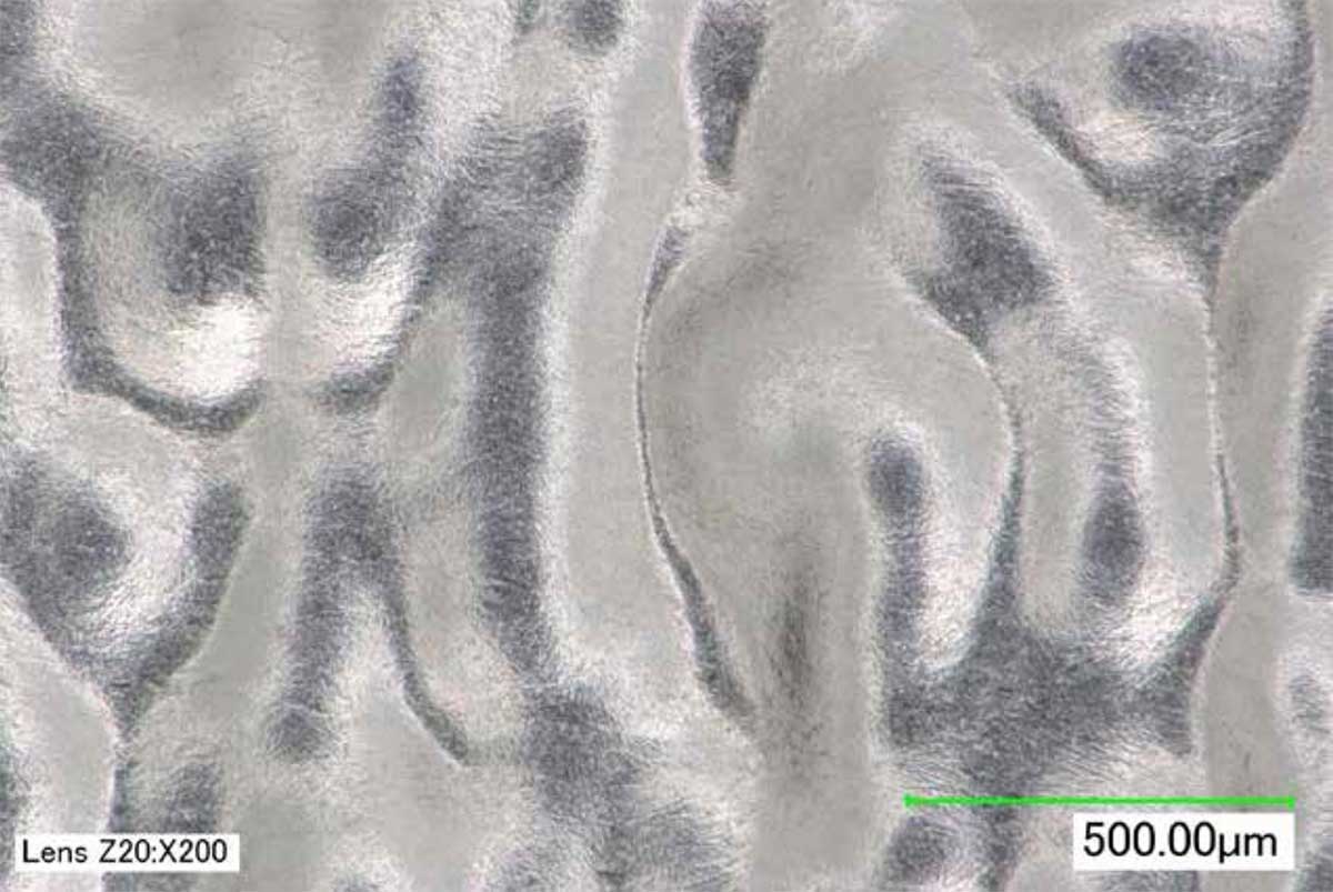
Fig. 5 Example of PBF-EB/Ti-6Al-4V micrograph showing high levels of residual waviness (Courtesy REM Surface Engineering)

Fig. 6 Comparative high-cycle fatigue testing results for PBF-EB/Ti-6Al-4V specimens with different surface finishes and finishing processes applied (modified from data provided by Northrop Grumman, UES Technology, and CalRAM Inc [6])
“In part due to the results of this earlier study, REM was contacted by JPL in July 2019 regarding the processing of PBF-EB/ Ti-6Al-4V components. The project yielded new and valuable data, as well as several potential flight components.”
From Proof of Concept to Collaboration with JPL
In part due to the results of this earlier study, REM was contacted by JPL in July 2019 regarding the processing of PBF-EB/Ti-6Al-4V components. The project yielded new and valuable data, as well as several potential flight components (see Fig. 7).
JPL sought to evaluate the effects, if any, of grit blasting and REM’s Extreme ISF Process on thin wall tensile strength. In addition, REM was asked to produce three distinct levels of roughness reduction to assess the impact of surface roughness on mechanical performance.
The results were surprising. Grit blasting led to a slight increase in yield strength and ultimate tensile strength (UTS), but no statistically significant improvement in elongation compared to as-built specimens (see Fig. 8). By contrast, specimens processed using REM’s Extreme ISF Process – first with CP, then CMP – showed significant increases in yield strength, UTS, and elongation relative to both the as-built and gritblasted samples.
Notably, these specimens underwent a uniform 500 μm of surface material removal (SMR), as specified by JPL, yet showed no statistically significant differences in tensile properties across the three surface roughness levels tested (6.4, 3.2, and 1.6 μm Ra) [7].
![PBF-EB/Ti-6Al-4V components for JPL, shown as-built and after surface finishing using REM's Extreme ISF Process [7]](https://www.remchem.com/wp-content/uploads/2025/07/metal-am-july25-fig7.jpg)
Fig. 7 PBF-EB/Ti-6Al-4V components for JPL, shown as-built and after surface finishing using REM’s Extreme ISF Process [7]
“The results were surprising. Grit blasting led to a slight increase in yield strength and UTS, but no statistically significant improvement in elongation compared to as-built specimens. By contrast, specimens processed using REM’s Extreme ISF Process – first with CP, then CMP – showed significant increases in yield strength, UTS, and elongation relative to both the as-built and grit-blasted samples.”
As Ti-6Al-4V was REM’s original and, at the time, primary metal AM material, this transition posed little challenge. Aluminium, however, was not a material REM frequently worked with in non-AM applications. The ISF Process typically excels on harder or more difficult-to-machine materials – hence REM’s focus on gears and steels outside of AM.
“The work yielded promising results, including insights into the importance of heat treatment and build parameters for achieving optimal bulk density. More importantly for JPL, it provided REM with a relatively mature surface finishing capability for A6061-RAM2.”
![Tensile testing results for PBF-EB/Ti-6Al-4V specimens with different surface finishes [7]](https://www.remchem.com/wp-content/uploads/2025/07/metal-am-july25-fig8.jpg)
Fig. 8 Tensile testing results for PBF-EB/Ti-6Al-4V specimens with different surface finishes [7]

Fig. 9 PBF-LB/A6061-RAM2 specimens shown in as-built condition and after processing with REM’s Extreme ISF Process (Courtesy REM Surface Engineering)
While REM had some ability to process traditionally fabricated aluminium, its low hardness means many other polishing methods exist, and aluminium accounted for only a small part of REM’s pre-AM business. As such, REM would have been poorly positioned to support JPL’s emerging need for A6061-RAM2 surface finishing – if not for a stroke of good timing (and Air Force SBIR funding).
In early 2020, following the successful completion of its first NASA Phase 1 SBIR, REM applied for an Air Force Open Call Phase 1 SBIR. Although some preliminary work had been done with PBF-LB/ AlSi10Mg, concerns about its as-built density persisted, and REM believed the Air Force was seeking a higher-performance aluminium. Aware of Elementum 3D’s emerging A6061-RAM2 material, REM proposed and won the SBIR to develop CP and CMP capabilities for it.
The work yielded promising results, including insights into the importance of heat treatment and build parameters for achieving optimal bulk density. More importantly for JPL, it provided REM with a relatively mature surface finishing capability for A6061-RAM2 (see Fig. 9).
Developing fixed processes for flight-ready components
To apply REM’s surface finishing capabilities to flight components, both REM and JPL needed a method to ensure consistent process control and repeatability. Since REM’s work introduced a subtractive manufacturing step, a material offset strategy also had to be defined.
REM proposed an ‘SMR [surface material removal] vs Roughness/ Texture’ study. This is a standard approach REM uses to help customers understand the expected surface condition for different SMR depths at given build angles. If the SMR intervals are sufficiently small, the study can also reveal any concentrations of subsurface porosity at specific depths.
JPL provided simple test specimens for the study, and REM processed eleven SMR levels using its CP method, each in triplicate, while documenting the resulting surface roughness and texture. These tests confirmed a concentration of near-surface porosity between depths of approximately 200-250 μm (see Figs. 10 and 11, noting the cluster of data points and higher standard deviations).
Since porosity itself was not a critical concern for this application, JPL and REM agreed on a standard offset of 165 μm for A6061-RAM2, just above the porosity band. This depth was sufficient to eliminate granular roughness and reduce surface waviness. Lower roughness levels were possible but would have required offsets exceeding 300 μm. With the material offset strategy defined, first for A6061-RAM2 and later for Ti-6Al-4V, REM began drafting Fixed Process documentation for both alloys.
Expanding CP to Aluminium and High-Performance Alloys
Drawing on its experience with aerospace gears, gas turbine engines, and life-critical medical devices, REM created a structure tailored to the requirements of metal AM.
![Scatter plot with trendline showing roughness versus SMR data for JPL's A6061-RAM2 material offset study [7]](https://www.remchem.com/wp-content/uploads/2025/07/metal-am-july25-fig10.jpg)
Fig. 10 Scatter plot with trendline showing roughness versus SMR data for JPL’s A6061-RAM2 material offset study [7]
![Scatter plot with trendline showing average roughness and SMR data with standard deviations for JPL's A6061-RAM2 material offset study [7]](https://www.remchem.com/wp-content/uploads/2025/07/metal-am-july25-fig11.jpg)
Fig. 11 Scatter plot with trendline showing average roughness and SMR data with standard deviations for JPL’s A6061-RAM2 material offset study [7]
“In traditional manufacturing, REM’s Fixed Processes are often part-number or part-family specific. However, JPL rarely produces the same component more than once, making this approach impractical in terms of both time and cost. Instead, with JPL’s agreement, REM developed alloy-specific Fixed Process documents.”
The goal of a Fixed Process is to define a repeatable and verifiable method, with the customer taking ownership of revision control. This ensures all parts supplied by REM are processed consistently and correctly, as documented in a Certificate of Conformance (C of C). For a Fixed Process to be effective, it must define:
In traditional manufacturing, REM’s Fixed Processes are often part-number or part-family specific. However, JPL rarely produces the same component more than once, making this approach impractical in terms of both time and cost.
Instead, with JPL’s agreement, REM developed alloy-specific Fixed Process documents. These define the most critical CP processing parameters for each alloy (see Table 1 for an excerpt from the Ti-6Al-4V Fixed Process summary table).

Table 1 Ti-6Al-4V process summary from JPL’s Fixed Process document (Courtesy REM Surface Engineering)
Given the wide range of part geometries JPL might send, these documents also include flexible application guidelines, offering multiple processing options and general advice on work holding. Specific details are confirmed with JPL on a job-by-job basis as required.
“Given the wide range of part geometries JPL might send, these documents also include flexible application guidelines, offering multiple processing options and general advice on work holding. Specific details are confirmed with JPL on a job-by-job basis as required.”
Lattices and Crush Structures for Mars Sample Return
In parallel to the Fixed Process development efforts, REM was also working with JPL on several experimental AM programmes. In 2020, Dr Ryan Watkins of JPL initiated what would become a multi-year effort with REM to develop AM crush lattices.
Dr Watkins was exploring the use of AM to produce crushable structures with more complex, optimised lattice geometries – designs that legacy manufacturing methods could not readily support. While AM’s geometric flexibility was key, challenges soon emerged, particularly around surface roughness and internal defects such as porosity.
Efforts within JPL to reduce roughness through build parameter modifications often led to an increase in internal defects. Additionally, despite the general geometric freedom of Powder Bed Fusion, Dr Watkins noted that AM ultimately struggles to achieve good length-scale separation at low relative densities due to limitations in minimum feature size. A different strategy was needed.
Drawing on REM’s prior work with JPL’s AM team, Dr Watkins reached out to trial REM’s CP process. The aim was to reduce surface roughness and remove near-surface flaws, such as porosity, that would otherwise lead to degraded or highly variable mechanical performance.
The initial trials were encouraging. Dr Watkins soon identified an expanded opportunity: to use CP not only for surface finishing, but to thin the lattice ligament diameters themselves. This would reduce component mass and relative density while also tuning the crush response, effectively using CP to overcome the inherent limitations of AM, including high surface roughness, poor near-surface quality, and limited resolution for fine features.
REM carried out multiple processing trials and coordinated part design modifications. The team ultimately succeeded in producing a honeycomb lattice additively manufactured in A6061-RAM2. The original ligament diameter was approximately 1.05 mm (see Fig. 12), which was reduced to below 0.15 mm (see Fig. 13) in the final ligament. These initial components achieved all performance targets set by Dr Watkins: reducing surface roughness by more than 50%, lowering relative density by over 75%, and improving crush strength and energy absorption efficiency by around 15% compared to traditionally manufactured honeycombs [9].
![As-built PBF-LB/A6061-RAM2 honeycomb lattice [9]](https://www.remchem.com/wp-content/uploads/2025/07/metal-am-july25-fig12.jpg)
Fig. 12 As-built PBF-LB/A6061-RAM2 honeycomb lattice [9]
![A6061-RAM2 honeycomb lattice after REM processing for extreme wall thickness reduction [9]](https://www.remchem.com/wp-content/uploads/2025/07/metal-am-july25-fig13.jpg)
Fig. 13 A6061-RAM2 honeycomb lattice after REM processing for extreme wall thickness reduction [9]
![As-built PBF-LB/A6061-RAM2 reflector [10]](https://www.remchem.com/wp-content/uploads/2025/07/metal-am-july25-fig14.jpg)
Fig. 14 As-built PBF-LB/A6061-RAM2 reflector [10]
Another application of the combined AM and CP approach was the development of submillimetre wavelength reflectors. As with the lattice structures, conventional manufacturing methods for these components impose significant limitations, particularly in terms of geometry and weight.
To overcome these challenges, JPL was investigating methods for printing smaller, cm-scale reflectors, and, more specifically, ways to generate lightweight backing structures (see Fig. 14). Based in part on the success of the earlier honeycomb lattice programme, REM’s CP process was trialled to remove as-built granular roughness and reduce component mass – and by extension, areal density, a key metric in space applications that expresses mass per unit surface area.
At the time, the state-of-the-art for reflectors under 20 cm in diameter was an areal density of approximately 14 kg/m². Using the AM + CP approach, JPL demonstrated a reflector with an areal density of around 13.4 kg/m², surpassing the existing benchmark. Notably, this result was achieved using only the standard 165 μm surface material removal (SMR) depth, suggesting that further reductions may be possible with more aggressive processing.
The reflector also featured a triply periodic minimal surface (TPMS) structure in its backing. This not only contributed to weight reduction, but also provided a useful test of material removal uniformity across a distinctly different geometry, further reinforcing JPL and REM’s confidence in the process (see Fig. 15) [10].
![PBF-LB/A6061-RAM2 reflector after Chemical Polishing [10]](https://www.remchem.com/wp-content/uploads/2025/07/metal-am-july25-fig15.jpg)
Fig. 15 PBF-LB/A6061-RAM2 reflector after Chemical Polishing [10]
![Concept design for the Mars Sample Return (MSR) Fetch Helicopter [11]](https://www.remchem.com/wp-content/uploads/2025/07/metal-am-july25-fig16.jpg)
Fig. 16 Concept design for the Mars Sample Return (MSR) Fetch Helicopter [11]
Another application that sought to apply Chemical Polishing to lightweight components was the development of prototype wheels for the Mars Sample Return (MSR) Fetch Helicopter. As part of the MSR mission, a vehicle is required to retrieve sample tubes from the Martian surface. One proposed concept is a small helicopter equipped with wheels to assist in sample collection (see Fig. 16). However, strict mission constraints dictated that each wheel must weigh no more than 20 g and measure less than 120 mm in diameter.
“The reflector also featured a triply periodic minimal surface (TPMS) structure in its backing. This not only contributed to weight reduction, but also provided a useful test of material removal uniformity across a distinctly different geometry, further reinforcing JPL and REM’s confidence in the process.”
To meet these constraints, JPL trialled several fabrication strategies for the prototype wheels, including Additive Manufacturing using A6061-RAM2 and hybrid microwaterjet cutting. Although the wheel geometries were not as complex as other components, such as reflectors or lattices, they were still subject to demanding material and performance requirements. JPL evaluated multiple design variations, some of which could only be realised through AM.
![Prototype MSR Fetch Helicopter wheels, shown as-built (left) and after Chemical Polishing (right) [11]](https://www.remchem.com/wp-content/uploads/2025/07/metal-am-july25-fig17.jpg)
Fig. 17 Prototype MSR Fetch Helicopter wheels, shown as-built (left) and after Chemical Polishing (right) [11]
Work on the lattice programme continued, and REM learned that these AM lattices were under consideration for use in the MSR mission. Contrary to prior assumptions, the Mars Samples – if and when returned to Earth – would not land via an arrested descent, such as a parachute. Instead, these high-value specimens would have to survive a terminal-velocity crash landing.
It’s worth noting that the work undertaken by Dr Ryan Watkins and the JPL team to enable this was significant. Beyond developing the lattices themselves, a web-based lattice design tool – Unitcell – was created to support the design effort. This tool, which has since been made publicly available, played a critical role in the project’s success by enabling the evaluation of multiple lattice architectures and unit cell sizes (see Fig. 18).
![Lattice design examples [9]](https://www.remchem.com/wp-content/uploads/2025/07/metal-am-july25-fig18.jpg)
Fig. 18 Lattice design examples [9]

Fig. 19 Large MSR crush lattice component: as-built top view (top left); as-built bottom view (top right); processed top view (bottom left); processed bottom view (bottom right) (Courtesy REM Surface Engineering)
Building on earlier work with PBF-LB/A6061-RAM2, REM and JPL began adapting the AM + CP process to the new Ti-6Al-4V lattice components. Due to the mission-critical nature of the application, extremely tight mass tolerances were required, typically ±1 g. While this was achievable for smaller components, larger lattices demanded mass reductions of over 80%, meaning the ±1 g tolerance represented less than 0.5% of starting mass. Achieving this level of precision required further refinement of REM’s process understanding and control systems.
Many chemical-based material removal processes are exothermic in nature. This is generally true for REM’s CP process as well, though the amount of heat generated varies depending on both the material and the surface area of the component(s). Ti-6Al-4V tends to generate a fair amount of heat during processing. However, for ‘typical’ AM geometries, REM can maintain the optimal processing temperature using a combination of active chilling and the natural heat sink effect of the CP solution’s working volume.
Lattice structures present additional challenges. Due to their high surface area, they generate significantly more heat during CP processing than non-lattice components occupying an equivalent ‘build box.’ As with many chemical reactions, the reaction rate – and by extension, the material removal rate – increases with temperature. In many ways, these Ti-6Al-4V crush lattices represented a ‘perfect storm’ of processing challenges.
Fortunately, JPL approached these challenges collaboratively. Over several months, progressing from small specimens to full-scale MSR components, REM and JPL refined the CP process to achieve repeatable results (Fig. 19). Full-scale lattice components reached final relative densities in the 1-3% range, down from as-built densities of 20-30%. This required the implementation of multiple process optimisations to tightly control material removal rates and ensure precise outcomes in ligament diameter, relative density, and component mass.
![Large MSR crush lattice component displayed at AMUG 2025 [14]](https://www.remchem.com/wp-content/uploads/2025/07/metal-am-july25-fig20.jpg)
Fig. 20 Large MSR crush lattice component displayed at AMUG 2025 [14]
“This collaboration is an example of how partnerships between research institutions and industry can support the development of solutions where commercial offerings are not readily available. In this case, JPL’s requirements led to the exploration of new processing capabilities that might not otherwise have been pursued.”
The success of the AM + CP – additive plus subtractive – manufacturing approach for the MSR crush lattices reflects JPL’s practical response to the limitations of current technologies. Where conventional options were insufficient, PBF-LB was used to produce components tailored to mission-specific requirements. However, limitations were discovered with the capabilities of PBF-LB, particularly in terms of resolution and material properties, such as surface roughness and near-surface density.
CP was identified as a potential means of addressing such challenges, and JPL collaborated with REM to adapt and scale the process for use with the crush lattice structures. This collaboration is an example of how partnerships between research institutions and industry can support the development of solutions where commercial offerings are not readily available. In this case, JPL’s requirements led to the exploration of new processing capabilities that might not otherwise have been pursued.
The much-deserved accolades that the MSR crush lattices have received through recent awards [12, 13], are a testament to the AM industry’s recognition of both the significance of this achievement and the value of further collaborations and projects of this kind. A direct benefit of this collaboration for REM has been the ability to apply the more advanced process controls and deeper process understanding developed during the lattice programme to AM heat exchanger applications, particularly large-scale components incorporating TPMS geometries and multiple domains.
Without the experience gained from the latticework with JPL, it is unlikely that these heat exchanger surface finishing and cleaning projects would have been as successful. Hopefully, public policy will continue to support the kind of research being undertaken by organisations such as NASA JPL – work that contributes not only to the AM industry but to the advancement of manufacturing as a whole.
Conclusion
Additive Manufacturing holds significant potential, but those working within the industry are well aware that it also comes with its own set of challenges. This is not unique to AM; all manufacturing technologies have inherent strengths and limitations. As with traditional subtractive processes such as machining, additional steps are often necessary to realise a component’s full performance potential. If aerospace gears can achieve a 3-5× increase in contact fatigue life through post-machining surface finishing, there is every reason to explore how post-processing technologies might similarly enhance AM components [15].
Acknowledgements
The authors would like to thank Andre Pate (formerly of JPL, now of General Atomics), Samad Firdosy, Dr. Ryan Watkins, Adrian Cheng, Dr. Doug Hofmann and the rest of the JPL team for their support and collaboration.
References
[1] Michaud, J. “Isotropic Superfinishing.” Gear Solutions, October 2015, pgs. 22 – 24.
[2] Hansen, B., Salerno, M., Winkelmann, L. “Isotropic Superfinishing of S-76C+ Main Transmission Gears.” AGMA Fall Technical Meetings, Orlando, FL, October 22-24, 2006. 06FTM02.
[3] Ehinger, R., Kilmain, C. “Evaluation of Isotropic Superfinishing on a Bell Helicopter Model 427 Main Rotor Gearbox.” American Helicopter Society 63rd Annual Forum, Virginia Beach, VA, May 1-3, 2007.
[4] “Bell Evaluates REM Surface Engineering and Selects ISF(r) to Enhance Critical Components.” REM Surface Engineering, September 18, 2020. Press Release. https:// www.remchem.com/news-item/ bell-evaluates-rem/
[5] Chavez, A., Baker, T., Fetty, J. “Future Advanced Rotorcraft Drive System (FARDS) Full Scale Gearbox Demonstration.” American Helicopter Society 73rd Annual Forum, Fort Worth, TX, May 9-11, 2017.
[6] Hayes, B., Porter, J., Velez, M., Hall, T., Davis, K. “Assessing the Tensile and Fatigue Properties of Ti64 Produced from Powder Bed Fusion Additive Manufacturing.” Material, Science, & Technology (MS&T17), October 8-12, 2017, Pittsburgh, PA, Conference Presentation.
[7] Michaud, J. et al, “A6061-RAM2: Novel Postprocessing Development to Enable Flight Hardware”, ASTM International Conference on Additive Manufacturing (ICAM), November 1-5, 2021, Anaheim, CA.
[8] “3D Materials.” Elementum3D, https://www.elementum3d.com/3dmaterials/. Accessed 13 June, 2025.
[9] Watkins, R., Duran, A., Comstock, E., Gori, M., Crocco, R., Hendry, M., Firdosy, S., Pate, A. “Tunable Additively Manufactured Impact Attenuation System for Entry, Descent, and Landing.” 2021. https://www.jpl.nasa.gov/site/ research/media/posters/2021/ R20109p.pdf
[10] Watkins, R., Goldsmith, P., Seo, Y., Firdosy, S. “3D Printed Submillimeter Reflectors: a New Design and Manufacturing Methodology.” 32nd IEEE International Symposium on Space THz Technology (ISSTT 2022), October 16-20, 2022, Baeza, Spain.
[11] Hofmann, D., Firdosy, S., Howe, S., Beatty, T., Moreland, S. Newby, M., Zuleta, M. “Pushing the Limits of Thin-walled Additive Structures for Use in Ultra-low Mass Rover Wheels for Planetary Exploration.” TMS 2024, 153rd Meeting & Exhibition, March 3-7, 2024, Orlando, FL.
[12] Petch, M. “2024 3D Printing Industry Awards Winners Announced.” 3D Printing Industry, December 17, 2024, https://3dprintingindustry.com/ news/2024-3d-printing-industryawards- winners-announced-235185/
[13] “Additive Manufacturing Users Group Names Technical Competition Winners.” AMUG, April 24, 2025, https://www.amug.com/ news/2025-technical-competition/
[14] Petch, M. “The Lattice that Might Save Mars Science: NASA JPL at AMUG Conference.” 3D Printing Industry, April 24, 2025, https://3dprintingindustry.com/ news/the-lattice-that-might-savemars- science-nasa-jpl-at-amug-conference- 2025-238800/
[15] Niskanen, P., Manesh, A., Morgan, R., “Reducing Wear with Superfinish Technology.” AMPTIAC Quarterly, Volume 7, Number 1, 2003.
Please fill out the information below to receive the selected resource.
Please fill out the information below to receive the selected resource.