

Fig. 1. 427 ISF processed input pinion.
This paper provides an evaluation of the processing and ef- fects of an improved gear tooth surface finish on the opera- tion of a Bell Helicopter Model 427 main rotor gearbox (MRGB). With superfinished gears, this gearbox was tested for thermal efficiency, gear tooth bending fatigue, extreme conditions operation, and acoustics. Testing such as the thermal efficiency testing and acoustic testing provides data that can be directly compared to gearboxes operating with standard finish production gears, while the gear tooth bending fatigue test and extreme conditions testing provide validation that the improved surface finish of the gear teeth and the chemical processing steps used were not detrimental to the integrity of the gears strength or operation.
TEST SPECIMEN
Testing was performed on a Bell Helicopter Model 427 main rotor gearbox. The Model 427 and 429 aircraft are shown in Fig. 2, while a 3-D model of the 429 main rotor gearbox, with similar configuration to the 427 gearbox, is shown in Fig. 3.
This gearbox has two engine inputs and is rated to provide a maximum continuous operating power of 800 hp (596 kW), with 400 hp (298 kW) per input, at 6,000 rpm (Ref. 2). Speed is reduced from 6,000 rpm to 395 rpm through two stages of reduction, including a spiral bevel set and a helical bull gear. Lubrication used in the gearbox conforms to DOD-PRF-85734 and is provided by an integral oil pump at a nominal pressure of 55 psi (379 kP). This oil is provided to the gear meshes using oil jets spraying a continuous flow of oil on both the in- and out-of-mesh sides of the gear mesh. A section of the gearbox is shown in Fig. 4, illustrating the reduction stages and the use of spiral bevel gears (input), helical gears (main rotor output), and spur gears (tail rotor output). All gears consist of Carpenter Pyrowear EX-53 gear material.
TEST STAND CONFIGURATION
The M427 development test stand, as shown in Fig. 5, is a mechanical regenerative and absorption type test stand using a 500 hp (372.8 kW) electric drive motor to provide the rotational speed and makeup power for stand and specimen losses. The regenerative torque loop consists of a series of test stand gearboxes and drive shafts that make a closed mechanical circuit. The test stand slave gearbox is designed such that independent torque loads may be imposed on each of the two inputs of the test specimen gearbox. Rotational actuators (ROTACS) adjust the torque within these two re- generative loops. The tail rotor output torque load is applied using a dynamometer. Mast lift and bending loads can be applied at the rotor hub end of the mast by hydraulic cylinders; however, these were not used in this testing.
The various test parameters indicated in the test plan were set and maintained with the use of instrumented and cali- brated transducers located on the test stand. All raw data was acquired by a computer-controlled data acquisition system, which served to transform the data into engineering units, provide a readout to the test stand operator, and store the data for future analysis.

Fig. 2. Bell Helicopter Model 427

Fig. 2. Bell Helicopter Model 429

Fig. 3. Bell Helicopter Model 429 main rotor gearbox (gear configuration same as 427).

Fig. 4. Bell Helicopter Model 427 cross section.

Fig. 5. Front and side views of the 427 MRGB test stand.
Test parameters are monitored using a combination of commercial instruments, such as flow meters and pressure transducers, and devices constructed by Bell Helicopter Textron Inc., such as load cells, torque transducers, and thermocouples.
The torque levels at which the test specimen gearboxes are operated are measured using strain-gage-instrumented shafts at various places on the test stands.
The Model 427 main rotor mast was instrumented with strain gages to read mast torque installed at mast stations 11.6 and 24.9 inches from the top of the mast.
Instrumentation was provided to monitor and record the following test parameters:
- Test cell ambient air temperature 2–4 feet (1 ± 0.3 m) from the gearbox.
- Transmission oil-in temperature.
- Transmission oil-out temperature.
- Oil-in flow rate.
- Time of day (local standard).
- Test time.
- Speed at each input.
- Torque at each input.
- Main rotor mast torque.
- Torque at tail rotor drive output.
- Transmission oil pressure.
- Chip detector indications.
- Vibration levels at both inputs, the tail rotor output, and the mast output using accelerometers in both the axial and radial directions.
The allowable tolerance on the recorded data was as follows:
Torque: ±2% of the full-scale value Speed: ±2% of the full-scale value Temperature:±4°F (±2.22°C)
Pressure: ± 2 psig (±13.7 kP)
Time: ± 30 seconds
Acquisition of all data was under the control of an automatic computer-controlled data system. Bell-developed software programs were used to acquire raw data from each of the active channels once per second. This data was used in real time to automatically shut down the test stand if preset limits were exceeded, to avoid damage to the test specimen. All active data channels were recorded by the satellite computer every second. To verify the integrity of the transmission gears during testing, inspections were performed at regular intervals via multiple inspection ports using a borescope to identify gear tooth damage or improper contact patterns.
ISF PROCESSING
Gears used for the testing had gone through all production gear finishing operations, including black oxide treatment, and had been run previously in the 427 MRGB for the qualification of bearings under a previous and unrelated test. These gears were not tested at elevated loads or extreme conditions prior to superfinishing. Additionally, no honing operations were performed on these gears as part of their production manufacturing processes.
All gear processing, including any required process development and tooling fabrication, was performed by REM Chemicals, Inc., located in Brenham, Texas. Prior to ISF processing, these gears were chemically stripped of black oxide and dimensionally inspected at Bell for adherence to Bell drive system design specifications and to provide a baseline to quantify the dimensional changes due to the ISF process. Dimensional inspection of the gear teeth included tooth profiles, circular tooth thickness, spacing, and surface finishes, while inspection of the roller bearing integral raceways included surface finish, roundness, and diameter. Magnetic particle inspection was also performed to validate gear integrity prior to fatigue testing. While one benefit of the ISF process is the ability to process entire gears for an improved surface finish, nearly all of the components in this test were partially masked prior to processing. This masking was performed in order to eliminate ISF processing on integral clutch races, ball bearing journals, and threads where it was determined that processing was not necessary and might require further process development outside of the scope of this testing.
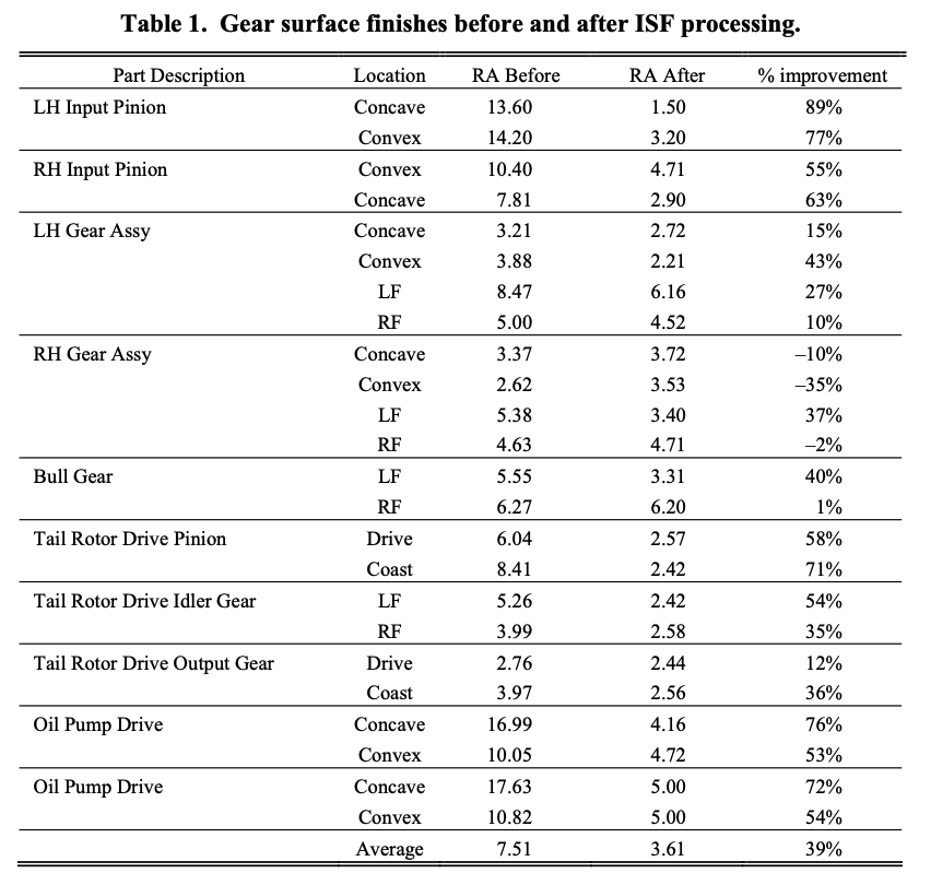
The surface finish improvements on the gear teeth as a result of the ISF processing are shown in Table 1. These results indicate that previous operation of the gears in a test envi- ronment had served to “run-in” the gear sets for an improved tooth surface finish prior to processing. This run-in indicates that the surface finish improved beyond the blueprint specifications for the gear teeth during gear operation, which is something that occurs at a lesser degree with ISF processed gears due to the increased gear mesh lambda ratios (Ref. 3). Despite the previous run-in, ISF refinement further improved the finish from an average of 7.51 μin to 3.61 μin Ra or an average of 39%. This finish of 3.61 μin Ra represents a finish that would be difficult or impossible to achieve using typical honing operations while maintaining proper gear geometry but was easily achieved using the ISF process. The most impressive improvement, 89%, in gear tooth surface finish is illustrated in the before and after surface finish traces shown in Fig. 6.
Review of all dimensional inspection data indicated that no significant changes were made to the gear tooth profiles or integral bearing raceways. Significant changes are those that would take the gear out of tolerance when dimensionally inspected. While as much as 0.0002 inch (0.00508 mm) was removed from each ISF processed surface, the material re- moval was distributed across the gear teeth and raceways so that parts remained within tolerance. To illustrate and quan- tify the change in the tooth geometry, a spiral bevel gear tooth was mapped using a Klingelnberg gear inspection ma- chine and the resulting before and after tooth surface maps are shown in Fig. 7. Note that while the geometry is shown to have changed due to the ISF processing, these changes reflect both an improvement and degradation in the gear tooth geometry and the change is not significant enough to take the gear tooth out of tolerance.
PRETEST ANALYSIS
Prior to testing, analysis was performed on the gear tooth meshes to analytically quantify the change in lamba (λ) ratio before and after the ISF processing. The lamba ratio is a measurement of the level and severity of the tooth to tooth interaction in the gear mesh. This lambda ratio is calculated using the method shown in Equation 1, where the lube film thickness is based on many factors, including the torque at the gear mesh, speed, temperature, and oil viscosity (Ref. 4). The composite roughness average is simply a sum of the roughness of the two gear teeth that are in contact in the mesh.
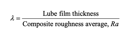
If λ < 1 then the thickness of the lubricant film is not more than the height of the surface asperities on the mating gear teeth, so metal-to-metal interaction leading to friction and noise will occur in the gear mesh. If 1<λ<2 then the thickness of the lubricant film is sufficient to provide some separation of the gear teeth; however, metal to metal contact is still possible between each gear tooth’s highest asperities. The goal in the optimization of gear meshes is to achieve a ratio of λ > 2, where full metal-to-metal separation is achieved, and even the highest asperities of the gear teeth are separated by a film of oil. This is known as elastohydrodynamic lubrication (Ref. 4)
Fig. 6. Surface finish traces taken before and after ISF processing (note reduced y-axis scale).


Fig. 7. Spiral bevel tooth mapping before (upper) and after (lower) REM Chemicals ISF processing.
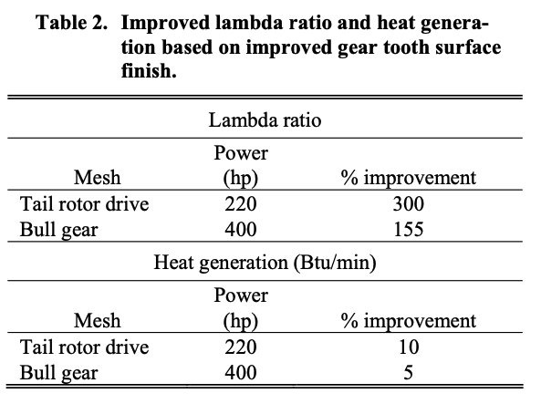
All operational aspects being equal, an improvement in the surface finish of the gear teeth results in an improvement in the lambda ratio. Achieving full metal-to-metal separation has benefits in efficiency, wear, and noise. Bell Helicopter in-house design tools based on AGMA standards were used to calculate the lambda ratios on both the helical gear mesh at the bull gear and the spur gear mesh of the tail rotor output. Lambda ratios were calculated at a power of 400 hp (Model 427 maximum continuous power) at each helical gear mesh and a power of 220 hp (Model 427 tail rotor transient) at the tail rotor spur gear meshes (298 kW and 149 kW, respectively). Baseline surface finishes were in accordance with the blueprint and were 8 μin Ra (pinion) (2032 μm) and 12 μin Ra (gear) (3048 μm) at the helical gear mesh and 16 μin Ra (4064 μm) at the tail rotor spur gear mesh. All surface finishes were analyzed at a conservative 4 μin Ra (1016 μm) for a post-ISF condition. Table 2 shows the analytical improvement in the gear mesh lambda ratios and heat generation, given the change in surface finishes of the meshing gear teeth.
It is important to note the significant improvements in the lambda ratio based on the improved gear tooth surface fin- ish. Though the bull gear mesh lambda ratio is still less than 1, this is due to the slow speed and high torque of the application evident in all rotorcraft final drive gear meshes, and improvements in the composite roughness average are not sufficient to fully negate the low lubricant film thickness.
The improvements in lambda ratio lead to a reduction in heat generation as a result of a reduction in the contact of the surface asperities in the gear mesh, resulting in less friction.
This improvement has also been published to reduce wear and noise in the gear mesh and is the reason that the ISF process and refinement of gear tooth surface fin ish improvements have merit in the aerospace industry (Ref. 3).
THERMAL EFFICIENCY
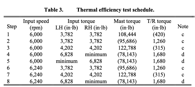
To provide heat rejection data and thermal efficiency data for the Model 427 ISF MRGB, test runs were performed in accordance with Table 3 at 170°F, 200°F, and 230°F ± 5°F oil-in temperature conditions (76.6°C, 93.3°C, and 110°C ± 2.8°C). For this test, the test cell ambient temperature varia- tions were minimized and no cooling air was used on the test transmission.
- Run load sequence at 170°F, 200°F, and 230°F ±5°F oil-in temperature.
- Table values in parenthesis are reference. Actual values are to be recorded. All other table values are specification points.
- Run time is that necessary to stabilize gearbox oil-out temperature to a rate of increase of 1°F in a 2-minute period.
- Hold for 30 seconds. Record the temperatures for the last 10 seconds.
- Lift and bending loads to be minimum required to stabilize the stand. Do not exceed 4500 lbs lift and 1,000 lbs shear.
- No hydraulic pumps are required.
In order to determine the thermal efficiency of the transmission, the oil flow rate, oil-in temperature, and oil-out temperatures were averaged for each of the run steps after temperatures had stabilized for two minutes. With the average flow rate, oil-in temperature, and oil-out temperatures, calculations could be made using the formula in Equation 2 to determine the heat generation of the transmission.
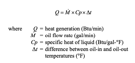
Because the specific heat capacity of oil changes with temperature, different values for specific heat capacity (Cp) are used in the equation for 170°F, 200°F, and 230°F ± 5°F oil- in temperature conditions (76.6°C, 93.3°C, and 110°C ± 2.8°C). Equations 3 through 5 shows the resulting equations given that the properties of Exxon Turbine Oil 25 [DOD- PRF-85734(AS)] are as follows:
170°F – a specific heat of 0.491 Btu/lb-°F (2.056 kJ/kg- °K) and a specific gravity of 0.950 at an average temperature of 174°F
• 200°F – a specific heat of 0.504 Btu/lb-°F (2.110 kJ/kg- °K) and a specific gravity of 0.938 at an average temperature of 203°F
• 230°F – a specific heat of 0.515 Btu/lb-°F (2.156 kJ/kg- °K) and a specific gravity of 0.928 at an average temperature of 230°F.
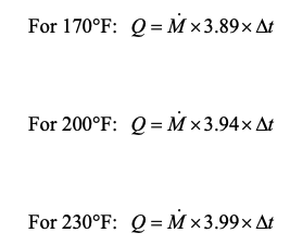
Figure 8 illustrates the Btu/minute heat generation of the Model 427 ISF MRGB for the load steps indicated in Table 3 at varying oil in temperatures. This chart indicates that at all operating conditions tested, the gearbox exhibited levels
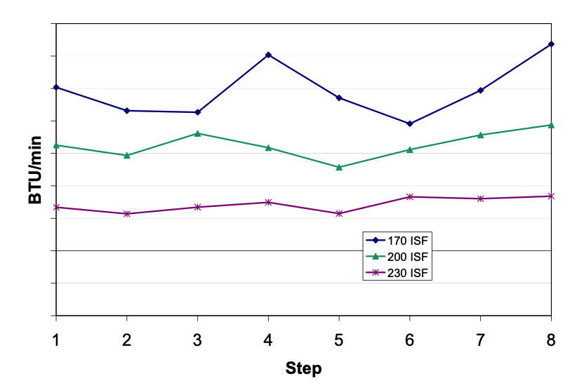
Fig. 8. Heat generation in the Model 427 ISF MRGB for varying load steps.
of efficiency comparable to previous Bell transmission testing. Baseline testing of a production-configured Model 427 MRGB is in work to quantify the difference in efficiency, expected to be less than ten percent, though published test data has documented as much as 30% reduction in gear mesh friction in unrelated testing as a result of ISF processing (Ref. 5).
GEAR TOOTH BENDING FATIGUE
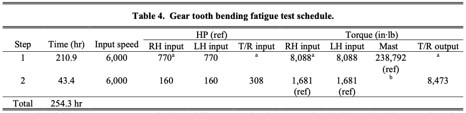
Because of the chemicals employed during the REM Chemicals ISF processing, and despite published coupon data indicating its positive (6% improvement) effect on bending fatigue properties, a gear tooth bending fatigue test similar to those used to qualify production rotorcraft transmissions was performed (Ref. 6). This full-scale fatigue test incorporated rolling, sliding, tooth bending, and transmission error factors that could not be accurately replicated through coupon testing. Additionally, this testing validated the process for use on both helical and spiral bevel gear geometries. The gear tooth bending fatigue test was scheduled to be accomplished according to Table 4. Since the original development and qualification testing of the Model 427 at 400 hp (298 kW) per input, the gears had been validated analytically to operate at Model 429 loads of 550 hp (410 kW) per input. Thus, for the purposes of testing and validating the ISF process, the Model 427 ISF MRGB was operated with the left and right inputs set at 140.3% of the 550 hp (410 kW) or 192.5% of its original maximum continuous rating.
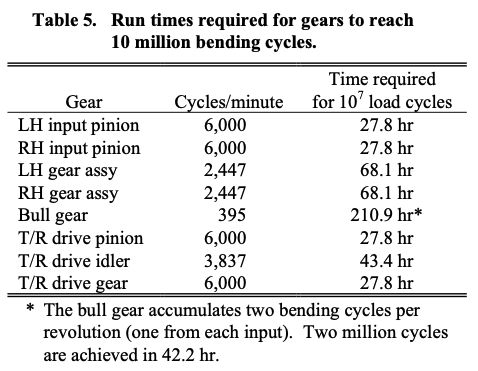
A schematic of the reduction ratios and speeds of the transmission gears is shown in Table 5. Table 5 summarizes the times required to accumulate 10 million bending cycles on each tooth of each gear in the transmission.
Due to test stand scheduling issues, the fatigue test was shortened to accumulate 2 million bending cycles on the bull gear. Because EX-53 material has a flat S-N curve after 2 million cycles, it was determined that a fatigue test to achieve the bending cycles indicated below was sufficient to demonstrate the process in fatigue.
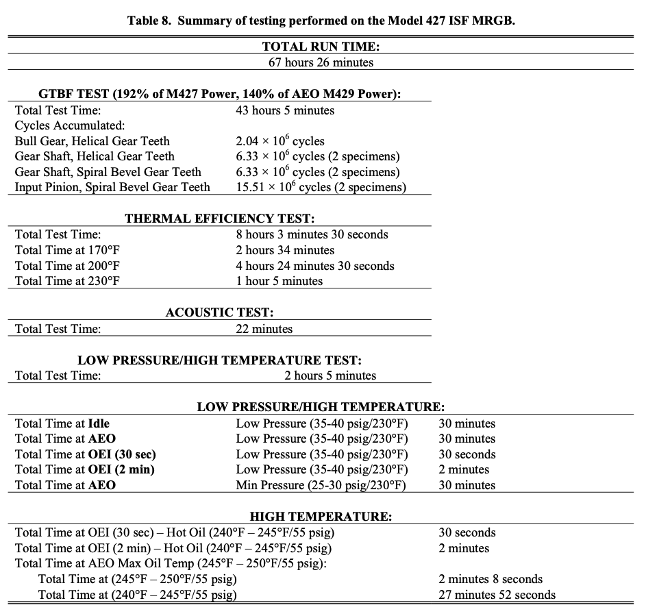
Total Gear Tooth Bending Fatigue Test Time: 43 hours 5 minutes
Cycles Accumulated:
• Bull gear, helical gear teeth 2.04 × 10⁶ cycles
• Gear shaft, helical gear teeth 6.33 × 10⁶ cycles (2 specimens)
• Gear shaft, spiral bevel gear teeth 6.33 × 10⁶ cycles (2 specimens)
• Input pinion, spiral bevel gear teeth 15.51 × 10⁶ cycles (2 specimens)
These cycles were accumulated without incident.
EXTREME CONDITIONS
While it stands to reason that an improved surface finish and increased lambda ratio will improve the operation of a gear mesh in low oil pressure and high temperature operation (where oil viscosity reduces and lambda ratios decline), some hypotheses predict that the near mirror finish of ISF gears lack the microscopic surface topography to hold and retain oil in extreme conditions, leading to scoring. To verify that an improved surface finish through ISF processing has no detrimental effect on operation in extreme conditions, an extreme conditions test was performed on the Model 427 ISF MRGB. During initial qualification of the production Model 427 MRGB, an extreme conditions test was performed to validate that scoring did not occur under the test conditions when tested at 400 hp (298 kW) per input. This testing was performed primarily at 550 hp (410 kW) maximum continuous power, with deviations including a full torque/low rpm condition and a high-torque/full-speed condition to simulate OEI (one engine inoperative) operation. Gears used in this testing were the same as those used in all previous efficiency and fatigue testing.
- Apply minimum TRGB torque required to stabilize test stand. The torque value for the RH input in step 1 above is to be increased by the amount of TRGB torque aplied to maintain 8,088 in-lb (770 hp) at the RH spiral bevel and helical gear meshes.
- Apply minimum transmission mast torque required to stabilize test stand.
- Maintain transmission oil-in temperature and tail rotor gearbox oil temperature at 160°F maximum.
- Transmission oil pressure shall be adjusted to 55 ±3 psi at 150°F to 160°F oil temperature.
- Reference: 100% speed = 6,000 RPM at transmission inputs and T/R output, 395.2 rpm at the mast, and 2,291 rpmat the TRGB output.
Low Oil Pressure Test
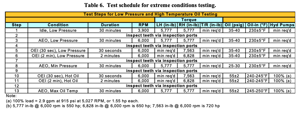
Runs were conducted for each condition, as shown in Table 6, with 35 to 40 psig (241.3 to 275.8 kP) oil pressure and 230°F ± 5°F (110°C ± 2.8°C) oil temperature based on the transmission’s allowable continuous operating range minimum of 40 psig (275.8 kP) oil pressure and maximum of 230°F (110°C) oil-in temperature.
A 30-minute run was also conducted at 550 hp (410 kW) per input with 25 to 30 psig (172.3 to 206.8 kP) oil pressure and 230° ± 5°F (110°C ± 2.8°C) oil temperature based on the transmission low pressure warning limit of 30 psig (206.8 kP).
Visual inspections through the viewing ports were made in accordance with the run schedule in Fig. 18. A final disas- sembly inspection was performed following completion of the high-temperature test.
The success criteria requires that no damage shall occur to the gear or bearing components, as determined in the final disassembly inspection following completion of the high-temperature test below. Visual inspection via the inspection ports during the testing indicated no gear tooth scoring or other anomalies were present during operation at these test conditions.
High-Temperature Test
After a visual inspection through the viewing ports following the low-pressure test, a high-temperature test was conducted at temperatures above the transmission’s normal operating range. These tests demonstrated gearbox operation at the corresponding temperature limits of the aircraft warning system as follows:
Normal Operation:
• 68°F to 230°F (20°C to 110° C)
Overtemp Warning: • >230°F (110° C)
The gear box was run at the test conditions indicated in Table 6 beginning at step 10. Operation for 30 minutes at temperatures exceeding 230°F (110°C) was performed based on an aircraft requirement to land as soon as possible if temperatures exceed the normal operating range of the transmission.
Visual inspections through the viewing ports were performed prior to the final 30-minute run to look for indications of scoring. Additionally, a final disassembly inspection was performed at the completion of the high-temperature tests.
The success criterion was that no damage shall occur to the gears or bearings, as determined in the final disassembly inspection. In fact, no scoring was present in the gearbox during the mid-test inspections or in the final disassembly inspection.
ACOUSTIC TESTING
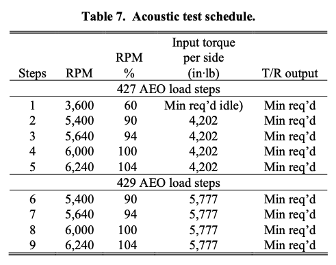
As an improvement in lambda ratio has been analytically verified based on an improved gear tooth surface finish, it stands to reason that a reduction in the tooth to tooth interaction will result in a reduction in the operating noise of the transmission (Ref. 7). In order to quantify the change in transmission noise at various operating conditions, the transmission was operated at the conditions listed in Table 7. These conditions represent the operating conditions of the subject gears in both Model 427 and Model 429 transmis- sions. By performing these tests with ISF-processed gears, we are able to document and catalog the noise signature of the transmission. Test results are pending baseline data, which is currently being performed on a production- configured transmission.
Analytical evaluation of the transmission noise was performed to evaluate the effect of ISF processing on the Model 429 helicopter cabin internal noise levels. Cabin internal sound pressure levels at 130 kn were analyzed with and without superfinishing. A noise reduction of 10 dB was applied at the transmission gear mesh frequencies based on the application of the ISF process as well as Bell Helicopter low noise grinding technology (Ref. 8). The decrease in noise levels at the main rotor gear mesh frequency and the input gear mesh frequency due to these technologies resulted in a 1 dB overall reduction in the cabin sound pressure level. Further testing is required to quantify the actual changes in transmission noise; however, analytical results represent a significant effect on passenger comfort through a reduction in cabin noise.
FINAL INSPECTION
Final visual inspection of the gear teeth was performed at several points during testing and at the completion of all testing. This visual inspection validated that the surface produced by ISF processing did not lead to scoring under the tested conditions and that no detrimental effect on gear tooth contact pattern was observed. Fig. 9 through Fig. 11 show specimen images that are representative of all gears removed from the gearbox and inspected.
TEST SUMMARY
Table 8 provides a summary of the testing that was performed on the 427 ISF MRGB to complete the defined testing.
CONCLUSIONS
1. ISF processing of production-configured Model 427 transmission gears resulted in no dimensional change to gear tooth profiles or bearing integral raceways significant enough to take the components out of tolerance.
2. ISF processing of production-configured Model 427 transmission gears that had previously been run-in resulted in an average surface finish change of 39% (7.51 μin Ra to 3.61 μin Ra).
3. Analytical evaluation of Model 427 gear mesh lambda ratios shows a 155–300% improvement based on blueprint surface finishes.
4. Analytical evaluation of gear mesh efficiency shows a 5–10% reduction in heat generation based on improved lambda ratios and blueprint surface finishes.
5. Gear tooth bending fatigue testing at 770 hp per input resulted in no gear tooth damage with 2 million bending cycles on bull gear and 15.5 million bending cycles on the input pinions.
6. Extreme conditions testing at low oil pressure (25 psi) and high oil temperature (250°F) resulted in no gear tooth scoring.
7. Analytical evaluation of potential gear mesh noise re- ductions (10 dB) shows a 1 dB reduction in cabin internal noise.
8. Final inspection of gear teeth and patterns validated the non-detrimental effect on tooth profile.
9. Final inspection of ISF processed integral bearing raceways and gear teeth indicated no scoring or abnormalities as a result of the cumulative 67.5 hrs of testing.
ACKNOWLEDGMENTS
Technical tasks described in this document include tasks supported with shared funding by the U. S. Rotorcraft industry and government under the NRTC/RITA Cooperative Agreement No. NCC2-9019, Advanced Rotorcraft Technology, January 1, 2001 and Army Technology Investment Agreement, W911W6-06-2-0002, NRTC Research Program. The authors would like to thank the NRTC-CRI organization for funding the test efforts in the development and validation of ISF processing technology for the rotorcraft industry, and REM Chemicals, Inc. for the processing of all Model 427 MRGB gear components, as well as technical support regarding the ISF process and published data.
REFERENCES
- Arvin, J., Manesh, A., Michaud, M., Sroka, G., Winkelmann, L., “The Effect of Chemically Acceler- ated Vibratory Finishing on Gear Metrology,” American Gear Manufacturers Association, October, 2002, Paper Number 02FTM1.
- Cope, Gary, “Model 427 Drive System,” American Helicopter Society 55th Annual Forum, Montreal, Quebec, Canada, May 1999.
- Nebiolo, William, “The Reduction of Parasitic Friction in Automotive Gearbox and Drive Train Components by Isotropic Surface Finishing”, Society of Automotive Engineers, December, 2002, Paper Number 02MSEC- 20.
- Townsend, Dennis P., Dudley’s Gear Handbook— The Design, Manufacture, and Application of Gears, McGraw-Hill, Inc., 1991, Pg. 15.8-15.10.
- Britton, R. D., Elcoate, C. D., Alanou, M. P., Evans, H. P., Snidle, R. W., “Effect of Surface Finish on Gear Tooth Friction,” American Society of Mechanical Engineers, Volume 122, January, 2000.
- Winkelmann, L., Michaud, M., Sroka, G., Swiglo, A., “Impact of Isotropic Superfinishing on Contact and Bending Fatigue of Carburized Steel,” Society of Automotive Engineers, Inc., 2001, Paper Number 2002- 01-1391.
- Houser, D., Vaishya, M., Sorenson, J., “Vibro-Acoustic Effects of Friction in Gears: An Experimental Investigation,” Society of Automotive Engineers, Inc., 2001, Pa- per Number 2001-01-1516.
- Hansen, B., Winkelmann, L., “Isotropic Superfinishing of S-76C+ Main Transmission Gears,” American Gear Manufacturer’s Association, October, 2006, Paper Number 06FTM02.


Download Resource
Please fill out the information below to receive the selected resource.